AwesomeEFIS installation
Mounting
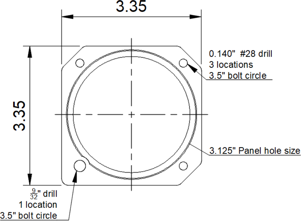
The EFIS mounts from behind the instrument panel into a standard 3 1/8" instrument opening. If mounting to a new panel use a standard instrument template to mark and drill mounting hole, or reference the panel cutout drawing below.
- Mount the EFIS with the included machine screws.
- Install the nut, and the washer if it fits. The thin washer is optional and may need to be left out, depending on panel thickness.
- Press the knob back on. Leave clearance between the panel and the back of the knob so the encoder button can be fully pressed.
Use 6-32 machine screws of the proper length. The mounting holes are 0.250" deep, so make sure the screws do not bottom out. 1/4" screws should work for most installations.
Pitot and static
The EFIS uses 1/4" push-to-connect fittings.
Recommended tubing is polyurethane with a 1/4" outside diameter and 5/32" inside diameter, such as McMaster-Carr part 5648K25. Make sure the tubing is not metric (6 mm), which is slightly smaller. Adapters can be used to convert from the 1/4" poly tubing to your aircraft's existing pitot / static lines. Use T-fittings as needed to plumb all instruments.
To install tubing:
- Cut the end of the tubing off square.
- Draw a reference line 5/16" (8 mm) from the end.
- Push the tubing into the fitting until it bottoms out. Use the line to verify it is fully inserted.
- Pull lightly on the tubing to test retention.
To remove tubing: slide the gray release collar in towards the fitting and pull back on the tubing.
Always trim before reinstalling
Never reinstall a tube that was previously installed without first trimming its end off.
Wiring
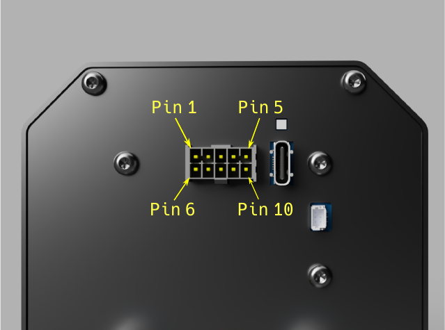
Connector pinout
| Pin | Function | Color |
|---|---|---|
| 1 | Voltage supply, switched | Red |
| 2 | RADbus high | Green |
| 3 | OAT return | Blue |
| 4 | No connect | |
| 5 | Termination enable | |
| 6 | Ground | Brown |
| 7 | RADbus low | Green / Black |
| 8 | OAT supply | Blue |
| 9 | No connect | |
| 10 | Termination enable return |
Power
Power the EFIS from a switched 9-36 V DC source with a 1 amp circuit breaker or fuse. The minimum connections are power and ground on pins 1 and 6, plus the GNSS antenna.
USB
Leave a USB-C cable connected to the rear of the EFIS, with the loose end secured behind the panel where you can reach it for firmware updates. Secure the cable to the main harness 3-4" behind the instrument with waxed lacing cord or a cable tie for strain relief.
Backup power source
A USB power bank can be used as a backup power source by connecting it to the USB connector on the rear of the instrument with a USB-C cable. The EFIS contains a power multiplexer that draws power from the aircraft's voltage bus by default. When the bus voltage falls below 5 V, the multiplexer switches to the USB port if a power bank is connected. The switchover happens automatically and the device stays powered throughout. When aircraft power is restored, the EFIS switches back to it.
The voltage on the PFD screen never shows the USB voltage. It continues to show the aircraft bus voltage while the EFIS runs from the USB backup, even though no current is drawn from the aircraft bus. During a battery or alternator failure you can turn off the avionics switch that feeds the EFIS if you want to. The displayed voltage will then be 0.0 V.
Never operate solely off USB
While the EFIS draws well below the minimum current supplied by a USB port (500 mA), it is not recommended to operate the device solely on USB power during normal operation. Always wire the EFIS to your aircraft's voltage bus.
If both USB and DC power are available, the EFIS uses the DC source.
GNSS antenna
Locate the antenna with a clear view of the sky. On top of the glare shield at the base of the windscreen is simple and effective, and a skylight or window also works. Reception is reduced if a metal panel shields the top of the antenna, for example when it is mounted under the glare shield.
RADbus
Leave the RADbus wires disconnected if this is the only RADaero device. To connect other devices, see RADbus.
Outside air temperature sensor
The included sensor is pre-terminated to pins 3 and 8. The polarity of the 2 wires does not matter. Outside air temperature sensor should be mounted in an area that is shaded from the sun by the aircraft, under a wing or fuselage. Be mindful of positioning relative to exhaust flow as this could alter the temperature reading.
To mount the sensor through the skin, drill a 1/2" hole, install the included grommet, and press the sensor into the grommet. To pass the wires through a bulkhead, de-pin the connector.
Another mounting location is in a cabin fresh air vent, a small slit in scat tubing will hold the sensor in place.
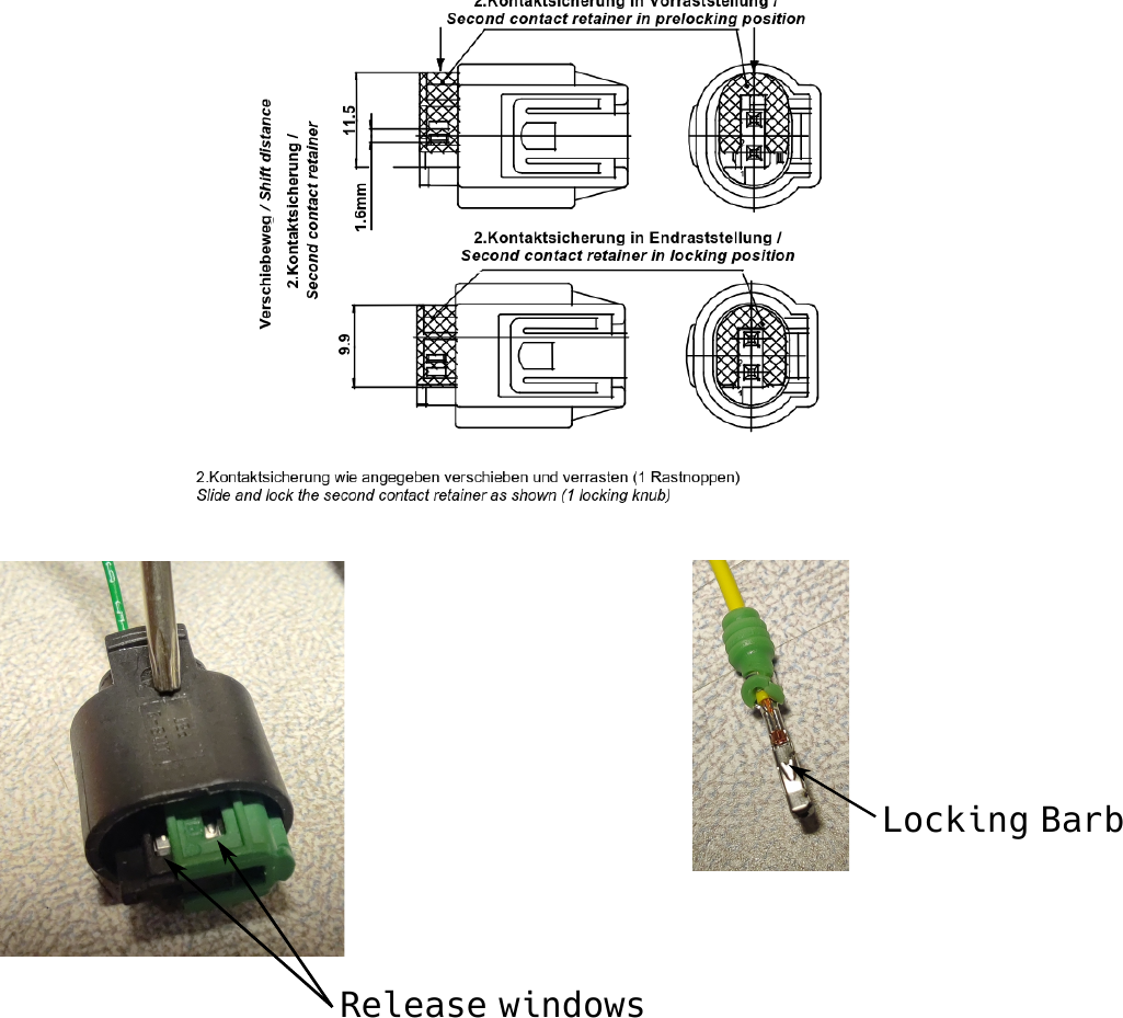
OAT sensor connector disassembly
- Slide the green contact retainer to the prelocking position. This exposes 2 windows where you can see the contacts.
- Use a small pick or tweezers to depress the contact locking barb while gently pulling the wire out of the housing.
To reassemble, push the contact into the housing until it locks, then slide the green retainer to the locked position.